There are a number of HI3518 camera module designs available on sites such as
Aliexpress. At least some of them, including the two modules I have got, have
FM24C08 (AT24C08) EEPROM chips on them. I thought I would give a go at reading
the EEPROM and also see if I could hook into the I2C lines and use them to
control other devices.
In my previous blog post
I managed to work out how to read the alarm pin found on the Hi3518 camera
module I have been playing with. With this worked out, I decided to combine the
Hi3518 with an HC-SR501 PIR sensor so that, with a bit of software written
based on the samples in the Hi3518 SDK, I could save images from the camera
whenever the PIR sensor detected motion. This worked well, so I ended up putting
together a waterproof enclosure to house the camera and sensor.
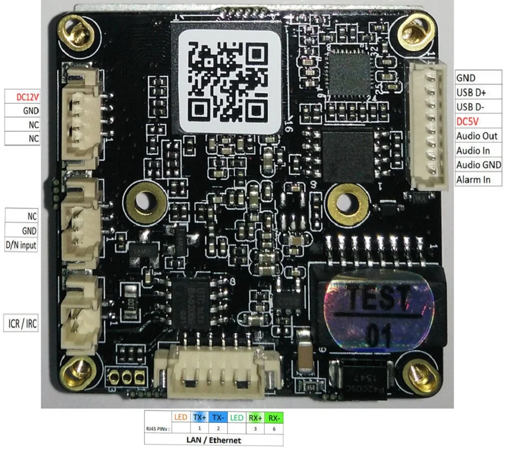
The HI3518 camera modules come in a range of designs. One common design has, in
addition to connectors for power, serial and ethernet, two connectors for
controlling an IR-cut filter, and a connnector that is shared by USB, audio and
and an alarm input.
The following is an image provided on an Aliexpress listing:
To make use of the IR cut and alarm features you need to know which pins on the
SOC they are connected to.
Pins
I managed to work out the following pins:
IR-cut (ICR/IRC): GPIO4_6/GPIO4_7
Day/Night sensor input: GPIO3_0
Alarm in: GPIO6_1
The IR-cut control uses two pins connected to a BA6208 reversible motor driver.
The day/night sensor input is designed to be connected to a light sensitive
resistor. The alarm input has a pull-up resistor and blocking diode.
Controlling GPIO Pins
There are two ways to control the GPIO pins: directly or using the GPIO Sysfs
Interface. In both cases you will need to refer to the HI3518 datasheet .
Direct Control
To control the pins using direct register writes you will need to configure the
function of the pins using the IO configuration registers (0x200F_xxxx) and
then configure the GPIO functionality.
An example of setting up the IR-cut filter pins you would use:
To flip the IR-cut filter in one direction you would use:
devmem 0x20180300 32 0x40
To flip the IR-cut filter back in the other direction you would use:
devmem 0x20180300 32 0x80
GPIO Sysfs Interface
Alternatively, you can use the GPIO Sysfs interface. For the GPIO Sysfs interface to work you will need to have compiled support
into the kernel.
If this is the case, you can then interact with the GPIO pins through the
/sys/class/gpio directory.
The first thing you need to do is work out the name of the GPIO pin in the
sysfs. The GPIO sysfs interface does not use the same names as the HI3518
datasheet for the pins. In the datasheet the pins are numbered in banks of 8,
but in the sysfs they are sequentially numbered.
You will need to use the following formula to work out the pin number:
sysfs_pin_number = bank_number * 8 + pin_number
For example, the alarm pin is GPIO6_1. This means it is pin 1 of bank 6.
6 * 8 + 1 = 49
Once you know this you can interact with the pin using the standard GPIO sysfs
interface. For example, to set up the alarm pin you would use:
You will notice the first command is using a direct write to the IO
configuration registers. I found this to be necessary even when using the sysfs
interface.
The HI35xx targeted version of buildroot I've been using in this series
of blog posts has support for an overlay filesystem. An init script
has been added to the skeleton filesystem that uses arguments provided through
the kernels command line parameters to mount the overlay. When it works, the
result is that the overlay gets merged into the root filesystem at boot.
However, I had some trouble getting it working.
Getting the Overlay Filesystem Working
The init script has been written to look for "overlay" and "overlayfstype"
arguments in the kernel command line parameters. The typical use case is that you
create a jffs2 partition on the flash and then set the "overlay" argument to
point to that partition and set the "overlayfstype" argument to jffs2. I gave this a go
but it did not work. After spending a bit of time investigating I realised the
init script was not getting run. The idea is that the init script should get
run as the first process and it should in turn run /sbin/init. However, it
looked as if the kernel was running /sbin/init directly and skipping the init
script. The solution was to explicitly tell the kernel to run the init script
using the "init" kernel command line argument.
An example of the resulting boot arguments I needed to pass to the kernel was:
In previous blog posts on the HI3518 I used an initramfs image, which combines
the root filesystem (rootfs) and the Linux kernel into a single image. Instead
of doing this you can also keep the root filesystem separate from the kernel
and use the command line parameters passed to the kernel at boot to tell it how
to mount the root filesystem. One option for where to store the root
filesystem is on a network file share (NFS).
Mounting an NFS Root Filesystem
When the HI3518 module boots the first thing that gets run is U-Boot.
If you have connected to the serial port on the module, you can press CTRL+C to
drop into the U-Boot prompt.
From there you can boot a kernel by:
Loading the kernel into RAM, usually from FLASH or TFTP
Setting the bootargs
Running the bootm command
An example of booting a kernel stored on a TFTP server and mounting an NFS root
filesystem would be:
The kernel will need to have been compiled with support for an NFS root
filesystem. If using buildroot run "make linux-menuconfig" and check
File systems > Network File Systems > Root file system on NFS
You need to set the nfsroot argument to point to the location of the NFS.
The kernel needs to have been compiled with support for auto configuring the
network. You can confirm this by checking:
Networking support > Networking options > IP: kernel level autoconfiguration
In this example the IP address of the HI3518 module has been set to a static
address of 192.168.2.2, it is also possible to use DHCP (see the kernel
configuration in the previous bullet point).
Attention needs to the paid to the comma separated list of NFS options
specified at the end of the nfsroot argument (i.e. "v3, tcp"). Getting these
wrong will cause the kernel to fail to mount the root filesystem. You may
need to use different options.
This is part 3 of a series of blog posts about a cheap HI3518 based camera module. In part 1, I showed how to build a custom image for the module. In part 2, I fixed a bug that was preventing the Ethernet from working. This part covers capturing an image.
Once I had built a custom image and got the Ethernet working I was ready to compile the HI3518 sample programs that are available in the SDK. To make this easier I set up an NFS share on my development computer and had the camera module automatically mount the share on boot up. This removed the need to include the programs in the image and so removed the need to build a new image each time I wanted to test a change to the programs, or the need to be constantly copying files around.
I was under the impression that the camera module I had contained an AR0130 image sensor. This is what the listing said, but it was also what the camera module reported in its boot logs. This however turned out not to be the case. I tried compiling the sample programs to target the AR0130 but could not get them to work. After a lot of playing around wondering what I was doing wrong I realised that the camera module I have actually contains an SC1035, which has a similar specification to the AR0130 but is not a drop in replacement. And, unfortunately the SDK did not include code for the SC1035.
The image below shows how you can distinguish between the two image sensors by looking at the layout of the contacts.
Comparison of the layout of the contacts of the AR0130 (left) and SC1035 (right)
This is part 2 of a series of posts involving a cheap camera module based on the HI3518 SoC, which is available on sites such as Aliexpress. In part 1 I described how to build a new Linux OS image for the module to replace the stock version of Linux that comes pre-installed on the module. The post ended with me showing how to boot the new image, but unfortunately on doing so I found that the Ethernet was not working, and this did not appear to be simply down to the need to configure it in the Linux OS.
It turned out that an issue about the Ethernet not working had already been added to the hi35xx/hi35xx-buildroot repository.
The issue appeared to describe the same problem I experienced, particularly the comment made by briaeros, which said:
"The led is barely orange when buildroot is "on" (as if there are not enough power).
On Uboot , it's brightly orange at start, then stay only green. And on the original firmware the two leds are brightly on."
The comments mention that you have to make sure that you have configured the Ethernet driver to either MII or RMII depending on how the Ethernet Phy chip has been connected to the HI3518. It is not possible to tell from looking at the circuit board how the HI3518 has been connected to the Ethernet Phy chip (in the case of the module I have, a IP101GR) so instead I booted in to the original Linux OS and checked the load3518.sh script. From this I determined that the module was using RMII. I then tried setting the CONFIG_HIETH_MII_RMII_MODE_U and CONFIG_HIETH_MII_RMII_MODE_D options in the Linux kernel to 1 (see the Solution section for how) as suggested in the issue. However this did not have any effect.
The comments in the issue also suggested looking at the boot options passed to the Linux kernel by U-Boot. However, this did not helped in getting the Ethernet working.
This post covers the steps I took to get the Ethernet working.
I recently purchased a cheap camera module off Aliexpress based on the HI3518 and the AR0130 image sensor. I plan for this post to be the first of a series covering this module. This post will cover how to build a basic Linux image and boot it. This will serve as the starting point for further exploring what the module has to offer and the quality of the images it produces. The aim is to build an image that can be booted without having to overwrite the existing OS (stored in flash), making the changes non-permanent and allowing you to boot back into the original OS at any point.
For my previous blog post Comparing the Theoretical Performance of Four Hackable Cameras I wanted to compare the performance of some image sensors using the values found in their datasheets. However, looking at the datasheets did not make their relative performance obvious, especially since the manufacturers do not always provide the information in a clear to understand format. So I had to work out how to calculate the read noise of each sensor using the numbers provided in the datasheets. In addition, I wanted to calculate a value for the signal-to-noise (SNR) that could be expected for a specific light level (in lux) and a specific exposure time.
In case it is of use to others I've created this calculator. The example buttons on the right hand side of the calculator can be used to see the exact numbers used for the four image sensor that were compared in the previous blog post.
Scene Reflectivity: the proportion of light reflected by an object in scene
Average Quantum Efficiency: the average proportion of light (photons) converted to signal (electrons) by the image sensor
How is the calculation performed
Estimating the read noise
Where read noise statistics are not provided by the manufacturer they can be estimated using the full well capacity and the dynamic range.
The dynamic range is calculated by dividing the maximum signal, which is the full well capacity, by the read noise.[1]
`drg = 20*log_10({fwc}/{rn})`
where:
`drg` is the dynamic range `(dB)`
`fwc` is the full well capacity `(e^-)`
`rn` is the read noise `(e^-)`
If the full well capacity is not stated in the datasheet it is usually possible to calculate it by using the maximum SNR figure often provided by manufacturers. This is the maximum SNR, which occurs when the signal is equal to the full well capacity.
`SNR_{max} = 20*log_10({fwc}/{tn})`
where:
`tn` is the total noise `(e^-)`
It is usually okay to assume that the total noise is dominated by the shot noise at the maximum signal.
`SNR_{max} \approx 20*log_10({fwc}/sqrt(fwc)) \approx 20*log_10(sqrt(fwc))`
Estimating the signal
To calculate the SNR it is necessary to estimate the number of electrons generated in each pixel during the exposure. To estimate the number of electrons generated, an equation was taken from the paper “When Does Computational Imaging Improve Performance?”[2].
Note: This calculation is an approximation but should be of the right order of magnitude.
`J = 10^15 (F//#)^{-2}tI_{src}R q\Delta^2`
where:
`J` is the number of generated electrons
`F//#` is the f-number of the lens
`t` is the exposure time
`I_{src}` is the incident illuminance in lux
`R` is the average reflectivity of the scene
`q` is the quantum efficiency of the sensor
`\Delta` is the size of a pixel in metres
Estimating Quantum Efficiency
For the values of the quantum efficiency (QE) it is usually necessary to estimate them from the charts put in the datasheets. For colour sensors, since each colour channel blocks approximately ⅓ of the photons, the QE can be approximated by taking the peak QE for the three colour channels and dividing by three.
Update (11/03/2017): If you are looking to calculate your own read noise and SNR values like those used in this comparison, take a look at the calculator I've created for the blog post Image Sensor Theoretical Performance Calculator.
I'm currently looking for a hackable camera for a project requiring relatively good low light level performance and at least a 1 megapixel resolution. I have identified four possible cameras but it is not immediately obvious which best fits my needs from looking at the datasheets. This post covers how I have gone about comparing the options.
The cameras are:
The Raspberry Pi OV5647 (2592 x 1944) based camera [1]. This is available as a module which has a built-in lens with an F-number of 2.9
The OV9712 (1280 x 800) which is available as a module that contains a hackable Linux based system using the HI3518. It doesn't have a fixed lens so can be fitted with a fast (low F-number) lens if desired
The AR0130 (1280 x 960) that is also available as an HI3518 based module. It doesn't have a fixed lens so can be fitted with a fast (low F-number) lens if desired
The MT9M001 (1280 x 1024) which is an interesting 1/2" monochrome sensor mentioned as compatible with the Arducam development platform[2]. Like the Raspberry Pi camera it also has a built-in lens which one datasheet suggests has an F-number of 2.8
To get an idea of the performance, I wanted to be able to compare their read noise values, as well as the signal-to-noise ratio (SNR) that could be expected for a specific light level (in lux) and a specific exposure time. In low light level conditions read noise usually dominates. However, the SNR value should provide a better idea of the expected quality of an image. An acceptable SNR for an image is typically taken to be 20dB and an excellent SNR for an image is 30dB+.[3]
To calculate the SNR value two pieces of information are needed: a value for the total noise and an estimate of the signal level, which is related to the amount of light collected by the image sensor and the efficiency by which the sensor converts it into a voltage. (Note: I have considered the read (temporal dark) noise and shot noise but not other sources of noise. For instance, in applications requiring a very long exposure time, thermal noise will start to become an important factor.)
Some manufacturers provide a value for the read noise however if this is not the case it is possible to work it out using the stated dynamic range and full well capacity of the sensor. Where the full well capacity is not provided this can be estimated using the maximum SNR value that some datasheets contain.
For the estimate of the signal level, the approach taken in the paper “When Does Computational Imaging Improve Performance?”[4] was used.
I wanted to get an impression of how these sensors would compare in low light levels with a exposure time of 0.005s. This exposure time was chosen based on a need to image a target moving at ~2m/s with a ground pixel size of 1cm. This means to prevent motion blur the exposure time would need to be in the range of 0.01/2s = 0.005s.
The resulting read noise and SNR values I calculated were:
Sensor
Read noise `(e^-)`
SNR value
OV5647
1.92
-6.94
OV9712
4.6
9.57
AR0130
2.00
15.09
MT9M001
12.30
9.80
Observations:
The SNR results suggests that the AR0130 would perform the best under the assumed conditions, while the Raspberry Pi camera (OV5647) would perform the worst. This is even though the OV5647 has the lowest read noise, suggesting that using the read noise values alone to compare cameras for low light level applications is not sufficient.
The read noise of the OV5647 and AR0130 were low at ~2e- while the read noise for the MT9M001 was much higher at 12e-. This is likely due to the MT9M001 being an older design.
The OV5647 has a low expected SNR even though it has the lowest read noise due to it's small pixel size and the high F-number of the built-in lens, which both result in a small signal (a small number of photons hitting each pixel)
It is possible to get the Raspberry Pi camera with a removable lens, which would allow for a faster (lower F-number) lens to be used. If the F-number is changed from 2.9 to 1.4, which is the same F-number used for the AR0130, the SNR increases to 3.44dB. This is still lower than the rest of the sensors due to the small pixel size on the OV5647
Another option for the Raspberry Pi camera is to bin the pixels. The resolution of the OV5647 is higher than the rest of the sensors by approximately a factor of 2 along each dimension. 2x2 binning of the pixels on the Raspberry Pi camera results in a resolution of 1296x1944, which is similar to the other sensors. Performing 2x2 binning results in a read noise for the combined pixels of `sqrt(1.92^2 * 4) = 3.84e^-`. Binning also results in a binned pixel size of 2.8`\mum`. Taking this into account the Raspberry Pi camera is still expected to perform worse than the AR0130, with a read noise and pixel size closer to the OV9712.
Based on these results I've purchased an AR0130 HI3518 based camera module to have a play with. I'll write another blog post covering how well it perform.
OpenCV is currently not available through the package system for the WR703N. This guide shows how to compile OpenCV from source using the OpenWRT toolchain.
This was carried out for the Attitude Adjustment (12.09-rc1) release of OpenWRT and release 2.4.4 of OpenCV.
If you are looking for the libraries and don't want to have to compile them yourself I have placed them on github: http://github.com/mark4h/openwrt