Introduction
There are a number of HI3518 camera module designs available on sites such as Aliexpress. At least some of them, including the two modules I have got, have FM24C08 (AT24C08) EEPROM chips on them. I thought I would give a go at reading the EEPROM and also see if I could hook into the I2C lines and use them to control other devices.
Getting the I2C Working
To get the I2C working the first thing I needed to do was work out which pins were being used. After a bit of playing I was able to work out that the I2C was using pins GPIO2_3 and GPIO2_5. The Hi3818 SOC does not have hardware I2C, instead these pins are used to perform I2C bit banging. The first step is to tell kernel about the I2C device. This is achieved by editing the file linux/linux-3.0.y/arch/arm/mach-hi3518/core.c.
First, you need to include the i2c-gpio header:
#include <linux/i2c-gpio.h>
Next, define the I2C device:
static struct i2c_gpio_platform_data gpio_i2c_pdata = {
        .sda_pin = 21,
        .scl_pin = 19,
        .udelay = 10, /* 50 kHz */
        // .timeout = 100,
};

static struct platform_device gpio_i2c = {
        .name = "i2c-gpio",
        .id = 0,
        .dev = {
                .platform_data = &gpio_i2c_pdata,
        },
};
Finally, initialise the I2C device by adding the following code to the to the end of the hi3518_init function:
// Register I2C
if (platform_device_register(&gpio_i2c) != 0)
    pr_warning("Failed to register i2c-gpio driver\n");
Before building the new modified kernel you also need to update the kernel configuration to build the required I2C modules, which are found under:
- Device Drivers > I2C support
- Device Drivers > I2C support > I2C device interface
- Device Drivers > I2C support > I2C Hardware Bus support > GPIO-based bitbanging I2C
Reading the AT24C08
Once the modified kernel has been build and the I2C modules included in the root filesystem, you can try to read the AT24C08. First you need to load the kernel modules:
# insmod /lib/modules/3.0.8/kernel/drivers/i2c/i2c-core.ko
# insmod /lib/modules/3.0.8/kernel/drivers/i2c/i2c-dev.ko
i2c /dev entries driver

# insmod /lib/modules/3.0.8/kernel/drivers/i2c/algos/i2c-algo-bit.ko

# insmod /lib/modules/3.0.8/kernel/drivers/i2c/busses/i2c-gpio.ko
i2c-gpio i2c-gpio.0: using pins 21 (SDA) and 19 (SCL)
At which point you should see an I2C device:
# ls /dev/i2c-0
/dev/i2c-0

# i2cdetect -l
i2c-0   i2c             i2c-gpio0                               I2C adapter
I found I needed to set the functions of the pins before the I2C would work:
devmem 0x200f002c 32 0x0
devmem 0x200f0024 32 0x0
At which point I could then run i2cdetect and find the EEPROM
# i2cdetect 0
i2cdetect: WARNING! This program can confuse your I2C bus
Continue? [y/N] y
    0  1  2  3  4  5  6  7  8  9  a  b  c  d  e  f
    00:          -- -- -- -- -- -- -- -- -- -- -- -- --
    10: -- -- -- -- -- -- -- -- -- -- -- -- -- -- -- --
    20: -- -- -- -- -- -- -- -- -- -- -- -- -- -- -- --
    30: -- -- -- -- -- -- -- -- -- -- -- -- -- -- -- --
    40: -- -- -- -- -- -- -- -- -- -- -- -- -- -- -- --
    50: 50 51 52 53 -- -- -- -- -- -- -- -- -- -- -- --
    60: -- -- -- -- -- -- -- -- -- -- -- -- -- -- -- --
    70: -- -- -- -- -- -- -- --
The AT24C08 uses the 4 addresses 0x50-0x53. Each of the 4 addresses references a 256 byte block.
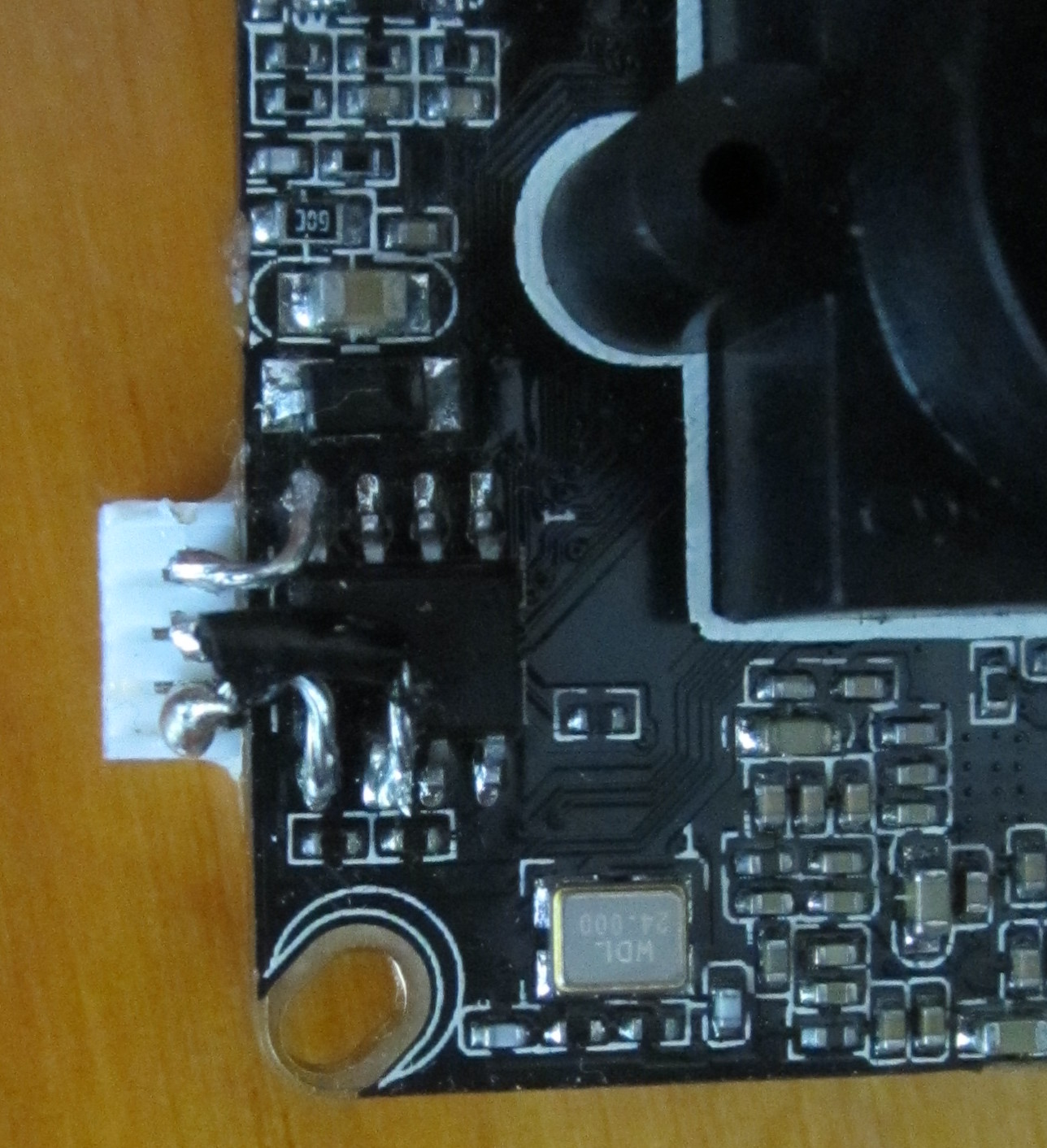
Connecting Additional I2C Devices
I soldered a connector onto the I2C lines so that I could use it to talk to other devices.
I was then able to plug in a DS1307 RTC module. The module also includes an AT24C32 EEPROM. After connecting RTC module, having modified it so that the AT24C32 is at address 0x57, I reran i2cdetect:
# i2cdetect 0
i2cdetect: WARNING! This program can confuse your I2C bus
Continue? [y/N] y
     0  1  2  3  4  5  6  7  8  9  a  b  c  d  e  f
     00:          -- -- -- -- -- -- -- -- -- -- -- -- --
     10: -- -- -- -- -- -- -- -- -- -- -- -- -- -- -- --
     20: -- -- -- -- -- -- -- -- -- -- -- -- -- -- -- --
     30: -- -- -- -- -- -- -- -- -- -- -- -- -- -- -- --
     40: -- -- -- -- -- -- -- -- -- -- -- -- -- -- -- --
     50: UU UU UU UU -- -- -- 57 -- -- -- -- -- -- -- --
     60: -- -- -- -- -- -- -- -- 68 -- -- -- -- -- -- --
     70: -- -- -- -- -- -- -- --
Testing the DS1307:
# i2cdump -y 0 -r 0x0-0x7 0x68
    0  1  2  3  4  5  6  7  8  9  a  b  c  d  e  f    0123456789abcdef
    00: 04 19 21 04 05 07 17 93                            ??!?????
No comments:
Post a Comment