Introduction
The HI3518 camera modules come in a range of designs. One common design has, in addition to connectors for power, serial and ethernet, two connectors for controlling an IR-cut filter, and a connnector that is shared by USB, audio and and an alarm input.
The following is an image provided on an Aliexpress listing:
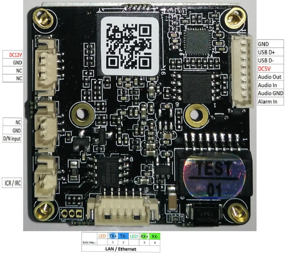
To make use of the IR cut and alarm features you need to know which pins on the SOC they are connected to.
Pins
I managed to work out the following pins:
- IR-cut (ICR/IRC): GPIO4_6/GPIO4_7
- Day/Night sensor input: GPIO3_0
- Alarm in: GPIO6_1
The IR-cut control uses two pins connected to a BA6208 reversible motor driver. The day/night sensor input is designed to be connected to a light sensitive resistor. The alarm input has a pull-up resistor and blocking diode.
Controlling GPIO Pins
There are two ways to control the GPIO pins: directly or using the GPIO Sysfs Interface. In both cases you will need to refer to the HI3518 datasheet .
Direct Control
To control the pins using direct register writes you will need to configure the function of the pins using the IO configuration registers (0x200F_xxxx) and then configure the GPIO functionality.
An example of setting up the IR-cut filter pins you would use:
devmem 0x200F004C 8 0x00
devmem 0x200F0048 8 0x00
devmem 0x20180400 8 0xC0
To flip the IR-cut filter in one direction you would use:
devmem 0x20180300 32 0x40
To flip the IR-cut filter back in the other direction you would use:
devmem 0x20180300 32 0x80
GPIO Sysfs Interface
Alternatively, you can use the GPIO Sysfs interface. For the GPIO Sysfs interface to work you will need to have compiled support into the kernel.
If this is the case, you can then interact with the GPIO pins through the /sys/class/gpio directory.
The first thing you need to do is work out the name of the GPIO pin in the sysfs. The GPIO sysfs interface does not use the same names as the HI3518 datasheet for the pins. In the datasheet the pins are numbered in banks of 8, but in the sysfs they are sequentially numbered.
You will need to use the following formula to work out the pin number:
sysfs_pin_number = bank_number * 8 + pin_number
For example, the alarm pin is GPIO6_1. This means it is pin 1 of bank 6.
6 * 8 + 1 = 49
Once you know this you can interact with the pin using the standard GPIO sysfs interface. For example, to set up the alarm pin you would use:
devmem 0x200F0084 8 0x0
echo 49 > /sys/class/gpio/export
echo in > /sys/class/gpio/gpio49/direction
You will notice the first command is using a direct write to the IO configuration registers. I found this to be necessary even when using the sysfs interface.
You can then read the GPIO pin state using:
cat /sys/class/gpio/gpio49/value
Hi Mark, Great findings as always! Thanks!
ReplyDeleteIn my experiments I ended up with similar (but not exactly the same) commands for switching the IR cut:
GPIO mux settings:
himm 0x200F004c 0x00000000 > /dev/null # muxctrl reg GPIO4_6
himm 0x200F0048 0x00000000 > /dev/null # muxctrl reg GPIO4_7
(I did not know about the 0x20180400 setting. It worked without it for my board)
switch IR cut on:
himm 0x201803fc 0x00000080 > /dev/null
usleep(20000)
himm 0x201803fc 0x00000000 > /dev/null
switch IR cut off:
himm 0x201803fc 0x00000040 > /dev/null
usleep(20000)
himm 0x201803fc 0x00000000 > /dev/null
I.e. I switch both lines of the complementary output to the same level after flipping the filter. The filter is delivered with my board is mechanically bi-stable.
Switching off the current was motivated since I noted in my experiments that SOFIA does the same. (I monitored the GPIO pin values during SOFIA startup, when the IR cut is flipped on/off in short sequence once).
I don't know if the IR cut magnetic coil may take thermal damage with continuous current, but since the filter is mechanically stable without continuous current, I would suggest to only shortly flip it with current pulse (some 10ms).
hi
ReplyDelete